Radio frequency energy in radar is
transmitted in short pulses with time durations that may vary from
1 to 50 microseconds or more. A special modulator is needed to
produce this impulse of high voltage. The hydrogen thyratron
modulator is the most common radar modulator.
|
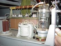
Picture 1: Thyratron Modulator |
|
As circuit for storing energy the
thyratron modulator uses essentially a short section of artificial
transmission line which is known as the pulse- forming network (pfn). Via the charging path this pfn is charged on the double
voltage of the high voltage power supply with help of the
magnetic field of the charging impedance. Simultaneously this
charging impedance limits the charging current. The charging
diode prevents that the pfn discharge himself about the
intrinsic resistance of the power supply again.
The function of thyratron is to act
as an electronic switch which requires a positive trigger of only
150 volts. The thyratron requires a sharp leading edge for a trigger
pulse and depends on a sudden drop in anode voltage (controlled by
the pulse- forming network) to terminate the pulse and cut off the
tube. The R-C Kombination is acting as a DC- shield an
protect the grid of the thyratron. This trigger pulse initiates the
ionization of the complete thyratron by the charging voltage. This
ionization allows conduction from the charged pulse-forming network
through pulse transformer. The output pulse is then applied to an
oscillating device, such as a magnetron.
The Charge Path
The charge path includes the primary
of the pulse transformer, the dc power supply, and the charging
impedance. The thyratron (as the modulator switching device) is an
open circuit in the time between the trigger pulses. Therefore it is
shown as an open switch in the picture.
Once the power supply is switched on
(look at the dark green voltage jump in the following diagram), the
current flows through the charging diode and the charging impedance,
charges the condensers of the pulse forming network (pfn). The coils
of the pfn are not yet functional. However, the induction of the
charging impedance offers a great inductive resistance to the
current and builds up a strong magnetic field. The charging of the
condensers follows an exponential function (line drawing green). The
self- induction of the charging impedance overlaps for this.
If the condensers are charged with
the power supplies voltage, decreases the current and the magnetic
field breaks down. The breaking down magnetic field causes an
additional induction of a voltage. This one continues the charging
of the condensers up to the double voltage of the power supply. Now
the condensers would discharged (ice blue curve) about the power
supplies resistance, but the charging diode cut off this current
direction and the energy remains stored therefore in the condensers.
The Discharging Path
When a trigger pulse is applied to
the grid of the thyratron, the tube ionizes causing the
pulse-forming network to discharge through the thyratron and the
primary of the pulse transformer.
Therefore, a current flows for the
duration PW through the pulse transformer therefore. The high
voltage pulse for the transmitting tube can be taken on the
secondary coil of the pulse transformer. Exactly for this time an
oscillating device swings on the transmit frequency. Because of the
inductive properties of the pfn, the positive discharge voltage has
a tendency to swing negative.
If the oscillator and pulse
transformer circuit impedance is properly matched to the line
impedance, the voltage pulse that appears across the transformer
primary equals one-half the voltage to which the line was initially
charged.