Tesla Coil 1Hutchisoneffect BannerTesla Coil 2

main image


Updated
Newsletter Blog Research Videos Photos Press Hoax

John Hutchison & Ronnie Milione

The Philadelphia Experiment Revisited!

TRANSMITTER REVIEW


The radar transmitter produces the short duration high-power rf pulses of energy that are radiated into space by the antenna. The radar transmitter is required to have the following technical and operating characteristics:

  • The transmitter must have the ability to generate the required mean RF power and the required peak power
  • The transmitter must have a suitable RF bandwidth.
  • The transmitter must have a high RF stability to meet signal processing requirements
  • The transmitter must be easily modulated to meet waveform design requirements.
  • The transmitter must be efficient, reliable and easy to maintain and the life expectancy and cost of the output device must be acceptable.

The radar transmitter is designed around the selected output device and most of the transmitter chapter is devoted to describing output devices therefore:

  
  • One main type of transmitters is the keyed-oscillator type. In this transmitter one stage or tube, usually a magnetron, produces the rf pulse. The oscillator tube is keyed by a high-power dc pulse of energy generated by a separate unit called the modulator. This transmitting system is called POT (Power Oscillator Transmitter). Radar units fitted with an POT are either non-coherent or pseudo-coherent.
     
  • Power-Amplifier-Transmitters (PAT) are used in many recently developed radar sets. In this system the transmitting pulse is caused with a small performance in a waveform generator. It is taken to the necessary power with an amplifier followingly (Amplitron, klystron or Solid-State-Amplifier). Radar units fitted with an PAT are fully coherent in the majority of cases.
     
  • A special case of the PAT is the active antenna.
    • Even every antenna element
    • or every antenna-group
    is equipped with an own amplifier here
     

Pictured is a keyed oscillator transmitter of the  radar unit.
The picture shows the typical transmitter system that uses a magnetron oscillator and a waveguide transmission line. The magnetron at the middle of the figure is connected to the waveguide by a coaxial connector. High-power magnetrons, however, are usually coupled directly to the waveguide. Beside the magnetron with its magnets you can see the modulator with its thyratron. The impulse-transformer and the pulse-forming network with the charging diode and the high-voltage transformer are in the lower bay of this rack.


The actual transmitter for the HUTCHISON-MILIONE Philadelphia Experiment will be somewhat different, but

STAY TUNED!

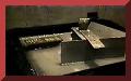
John Hutchison's miniature Philadelphia Experiment July 2006 Philadelphia Experiment button 
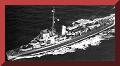
The Philadelphia Experiment to be Revisited by Ronnie Milione and John Hutchison Destroyer button
John Hutchison's miniature pretest of the equipment. Pretest of the Philadelphia Experiment button 
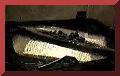
This is a clip of the standing waves John created in the water. Standing waves button

Lightning Vandegraph

Google